A big turn out thanks to good weather.


A big turn out thanks to good weather.
The August jet day didn’t happen due to bad waether, but it was dry for September


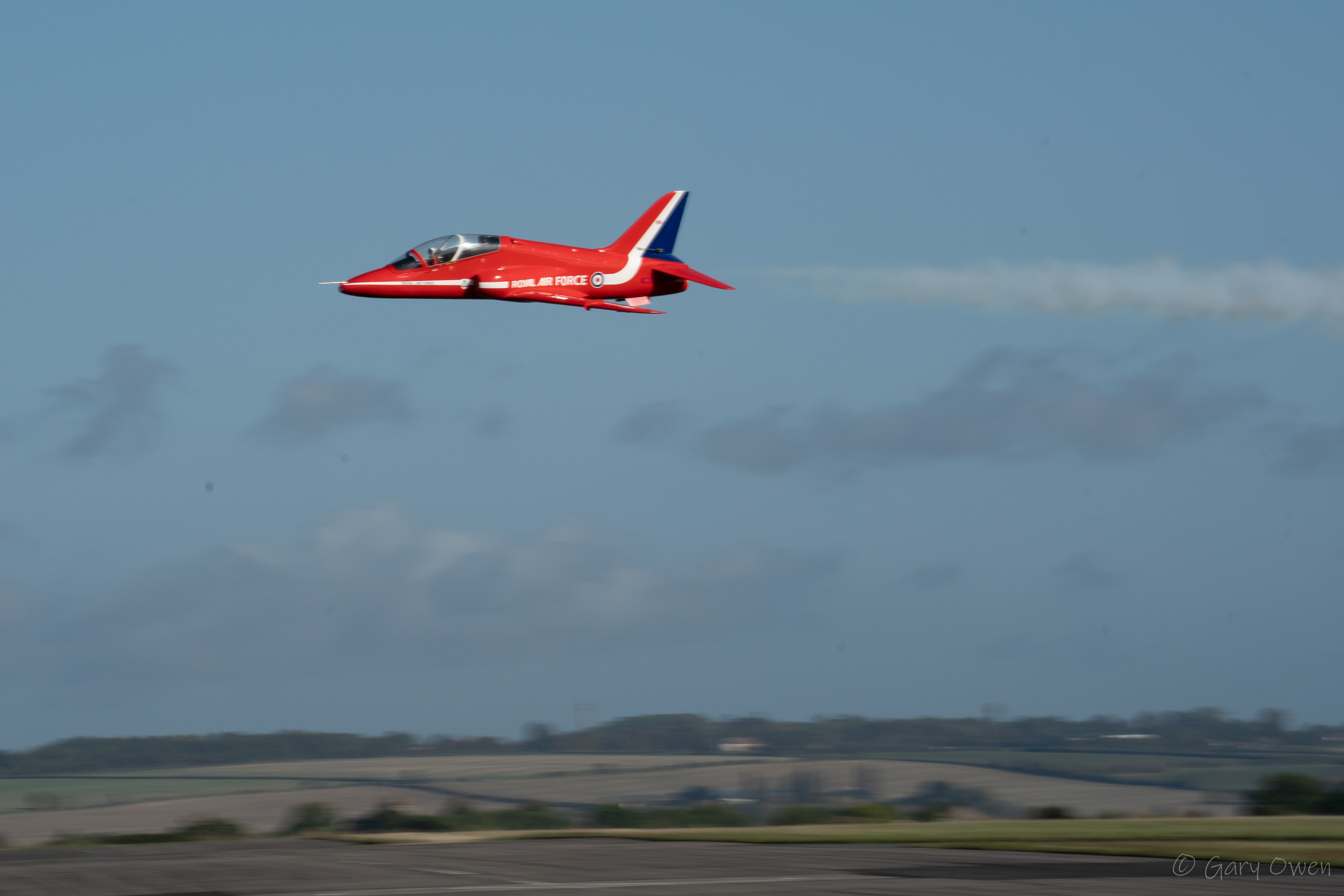
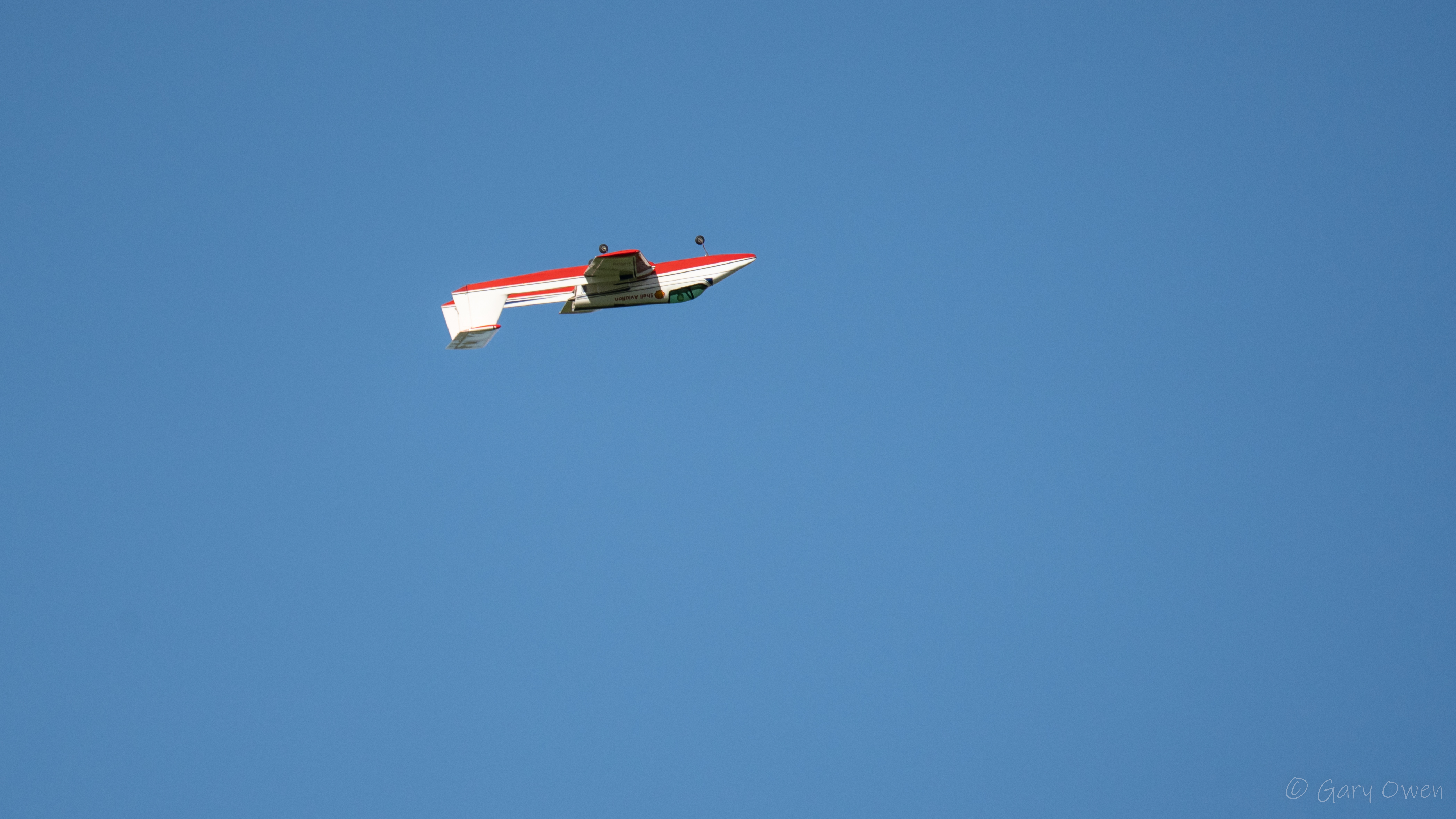
Jet flying takes place one day a month, due to noise restraints with the local community. On non jet days, there is still good flying to be seen.


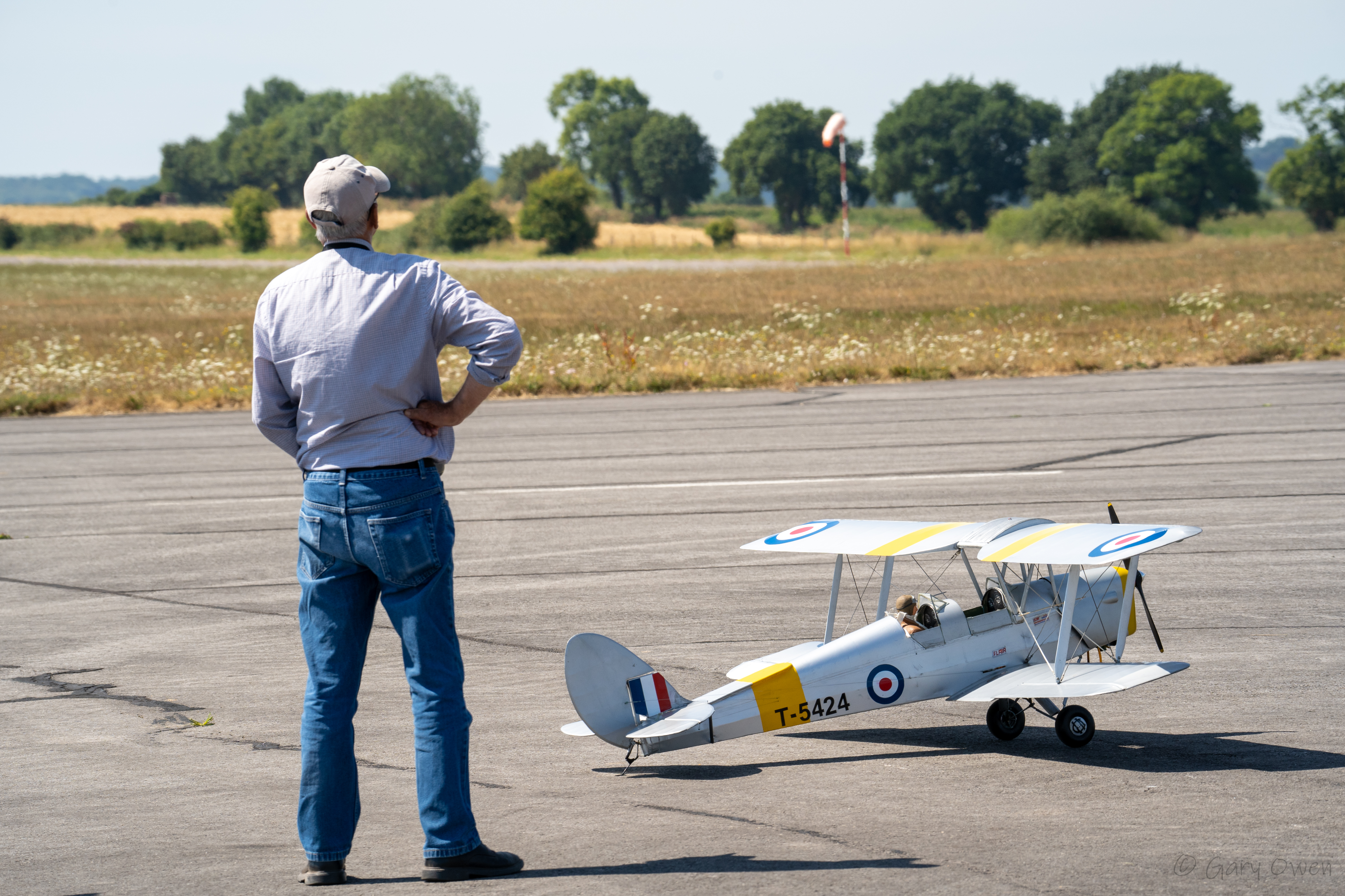


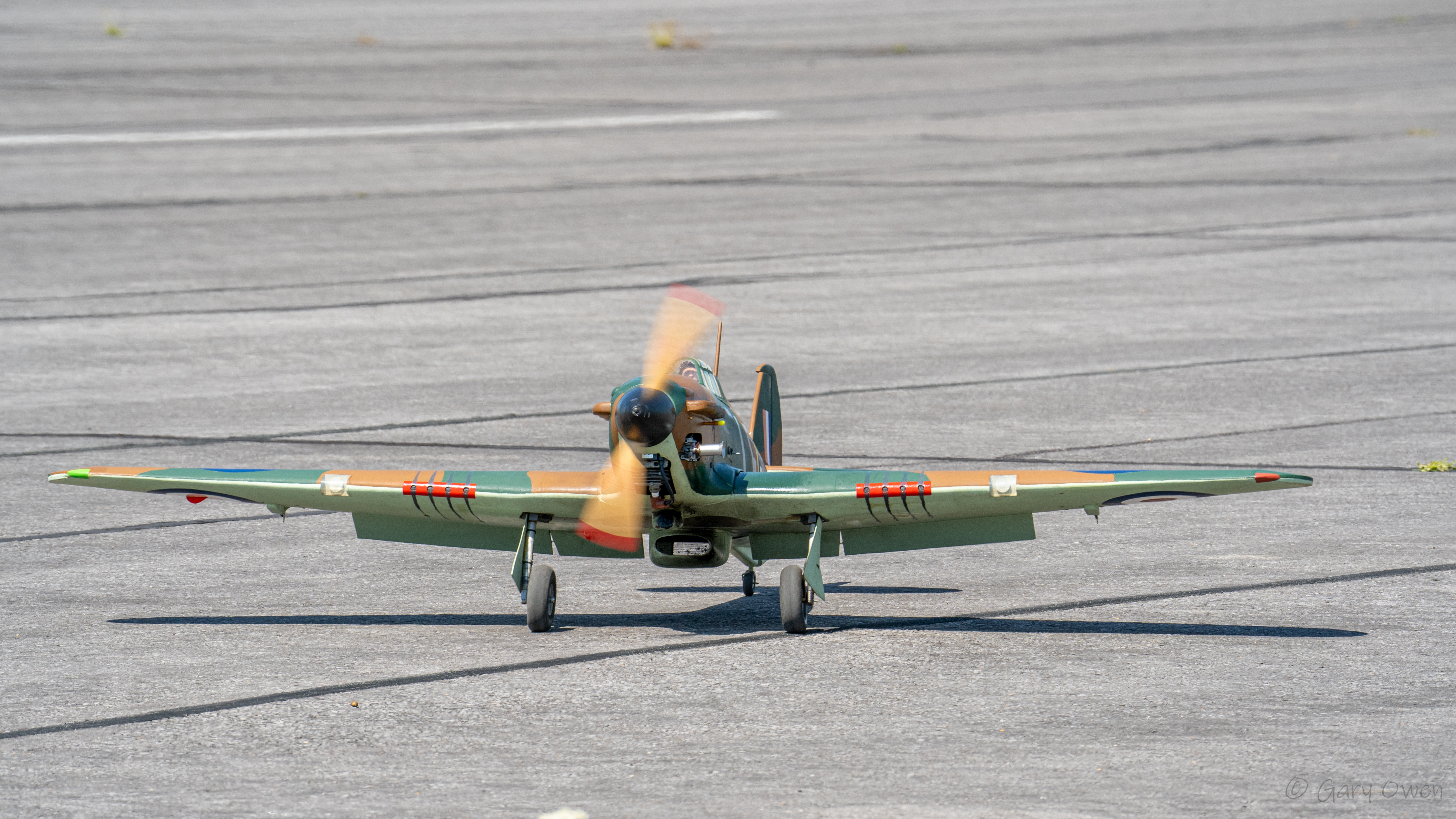


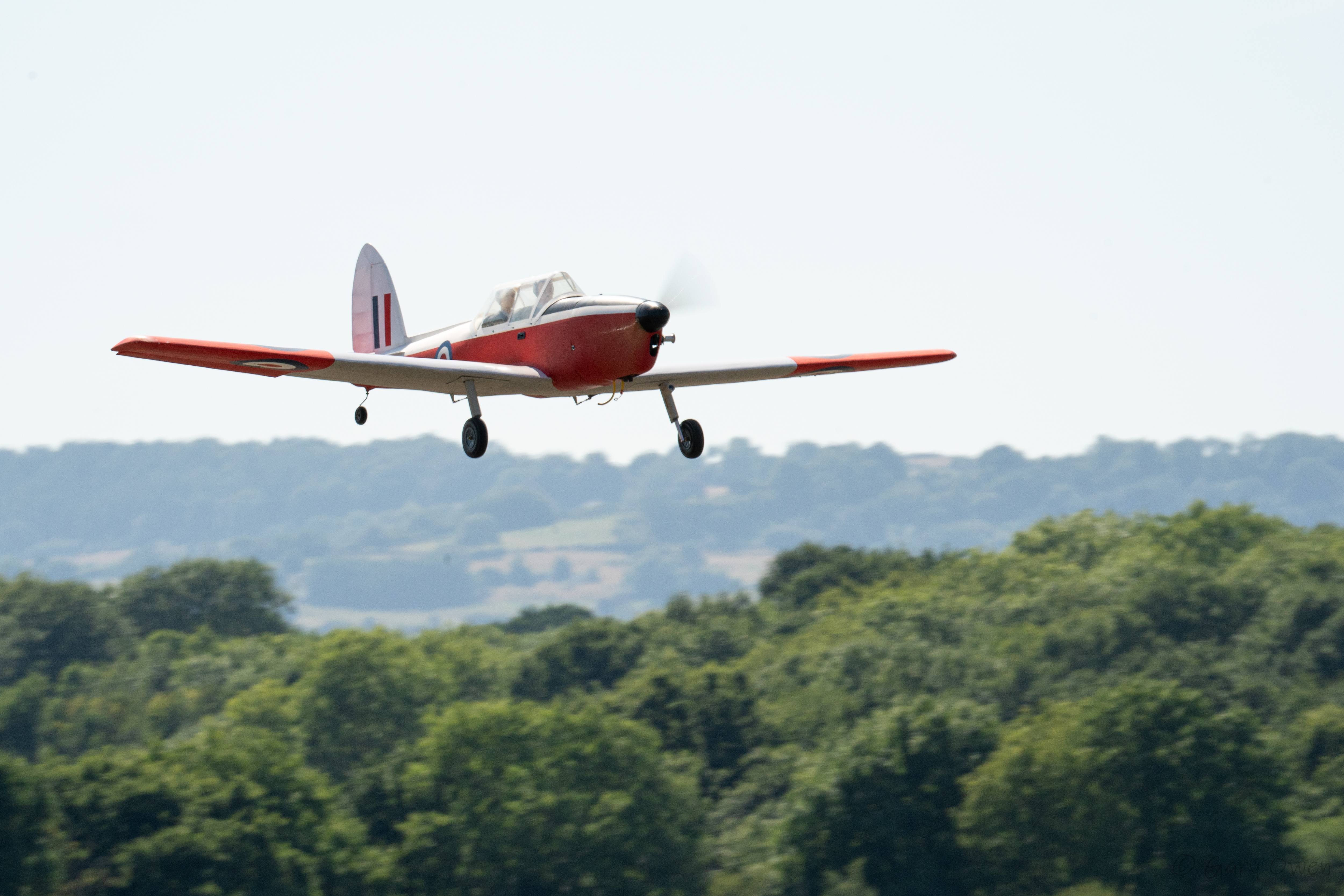


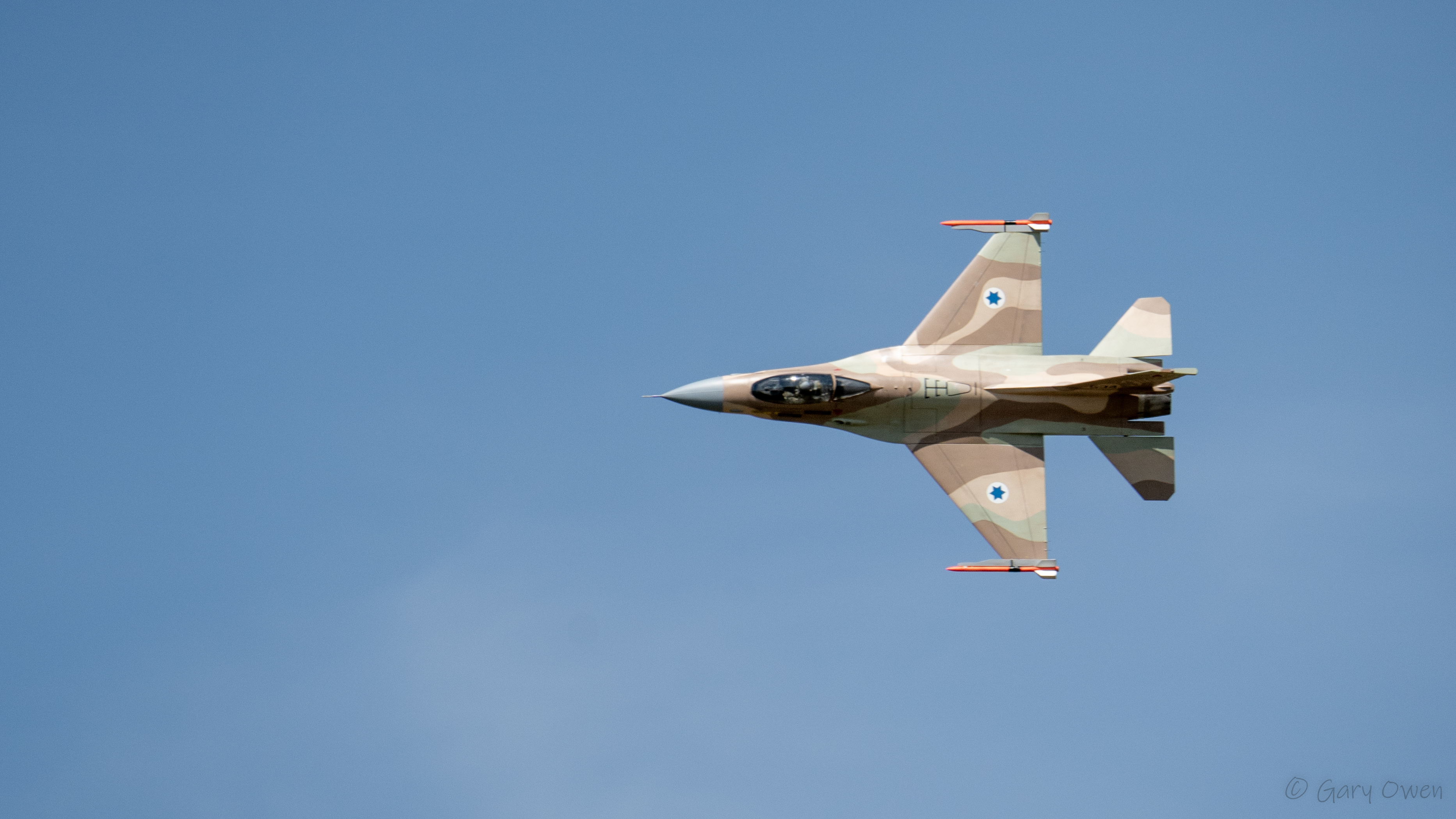
Here are some photos from the July Jet Day at Merryfield.


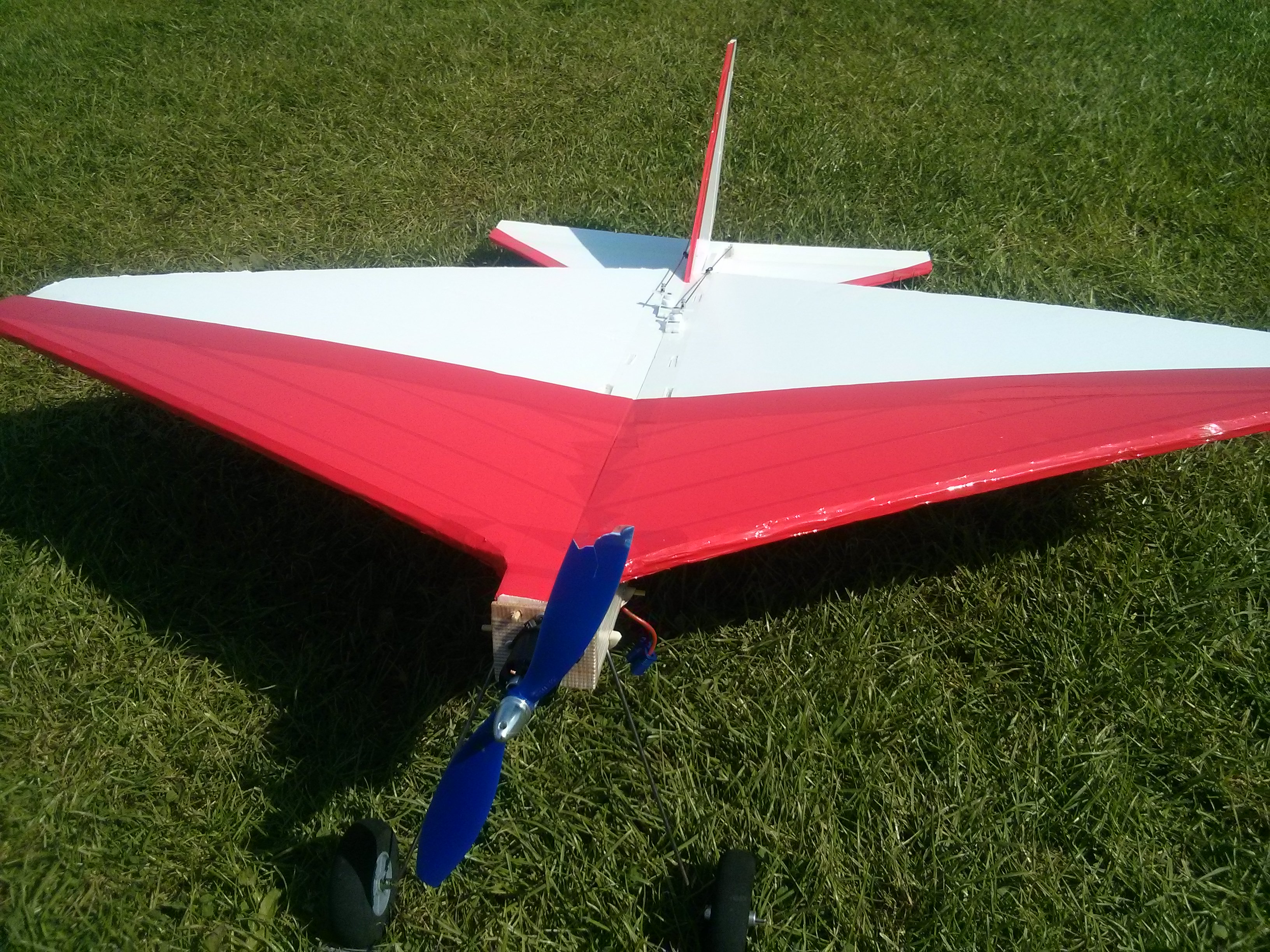
Foam board has become a common material for scratch building RC aircraft. Flitetest.com provide a good range of free plans using this material. The problem is that the foam board available outside the USA is significantly heavier than that on which the designs are based. This leads to heavy fast flying planes that are not beginner friendly. This article looks at two enlarged FT designs that restore the good flying qualities of the original designs.
Flitetest.com (FT) has been around since 2010 publishing high quality video episodes on all aspects of radio control flight. They are strongly focused on community with forums refreshingly free of negativity. They are well known for their range of free plans with designs from beginner to advanced each with a dedicated build video.
The main build material is foam board, which consists of a polystyrene core sandwiched between two layers of paper. You will see it referred to by names like Dollar Tree foam board or DTFB, Bazics foam board and Adams Ready-Board which is the American manufacturer. Other makes of foam board are available, but tend to be significantly heavier. Adams Ready-Board is not freely available outside the United States, so the rest of the world has to be content with the heavy stuff.
To give some idea of the problem Adams Ready-Board weights 297 g/m². The lightest foam board I have found in the United Kingdom weighs 450 g/m², with some sheets reaching almost 600 g/m².
Before I was aware of this, I bought two 10 sheet boxes of A1 foam board: one in black the other white. I used the black to build an FT Nutball and the white to build an FT Flyer. both are beginner designs. Having used the recommended electronics, with a 2S 500 mAh battery, I was surprised to find both designs exceedingly tail heavy. By using a bigger motor and heavier 3S 1300 mAh battery, I was able to get the centre of gravity (CofG) in the right place, but the models were now twice the design weight. They did fly, but were very fast and not really suitable for a beginner.
There was no way I could reduce the weight using the same foam board, but having only used two sheets out of twenty I didn’t want to buy anything else. Heavy models are not necessarily bad. The problem is the weight in relation to the model’s size or more specifically the wing area. This is expressed mathematically as the wing loading, defined as the models weight divided by its wing area.
The total weight is made up from two parts. There is the airframe weight which will increase with the wing area. Then there is the battery, motor and control electronics. As I was already using a bigger battery and motor to get the heavy foam model to balance, this could stay the same. As the fixed component is a large part of the total, the wing loading will decrease with increasing wing area.
The design weight of the FT Nutball is 212g plus 30.5g for the battery. The wing is 490mm diameter. Therefore the wing loading is (212 + 30.5 ) / (3.142 x 490² / 4) = 0.00128 g/mm² or 1.28 kg/m².
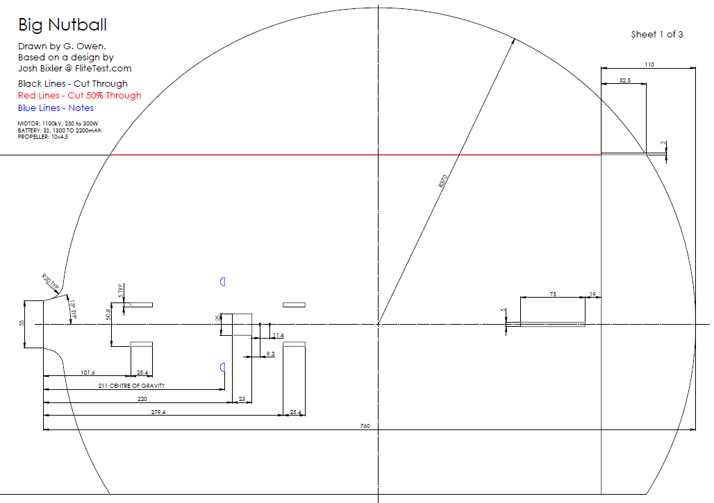
It turned out for the Nutball that increasing the diameter to 740mm reduced the wing loading back to 1.28 kg/m² using the same electronics. This was also a good size for cutting the model from two A1 sheets. I kept the power pod the original size, but moved it forward slightly to help maintain the CofG position.
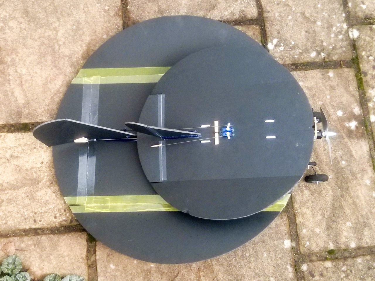
Size comparison of Big Nutball to original FT Nutball.
Big Nutball Full Size PDF Download
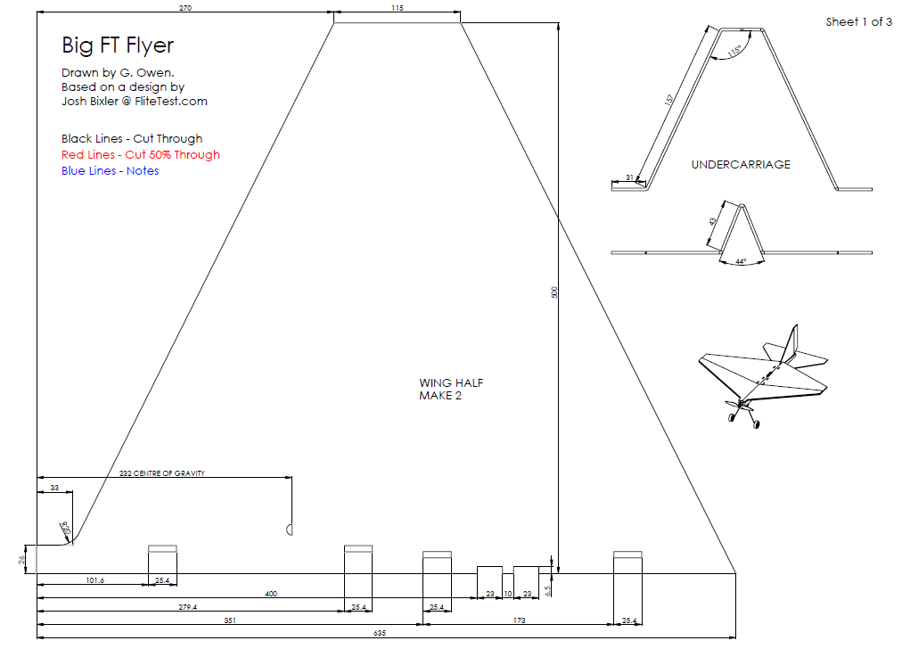
The plans have dimensions for those without access to an A1 plotter or don’t want to stick together the tiled A3 prints. Construction follows the original video. You just need to tape on the port wingtip before gluing and use the included gauge instead of the power pod for setting the dihedral.
The push rods are long so use three zip ties to keep them straight.


The big Flyer design followed the same procedure. The original target wing loading was 1.69 kg/m² with its 660mm span. Increasing the span to 1000mm got the wing loading down to 1.65 kg/m² with the heavy foam board. Again I extended the nose to ease the CofG placement.
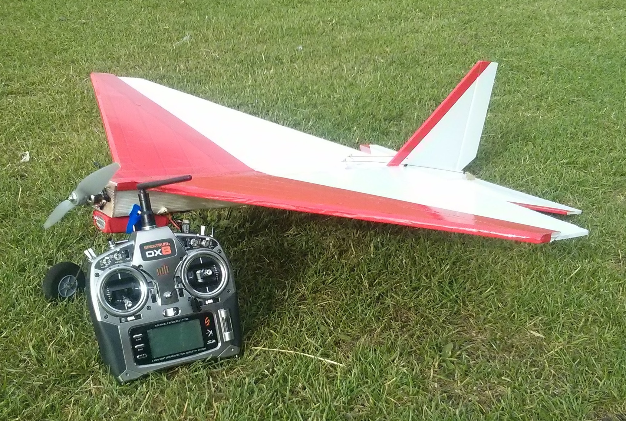
In a departure from the original I added was a KF step. This is an extra thickness of foam added to the front 40% of the wing, with the it’s leading edge chamfered 45°. An air bubble forms behind the step, causing the wing to more act like a proper airfoil with more lift and smoother pitch response. The KF step is optional, but I have been very pleased with its performance and deem it worth the weight. The extra thickness also makes the wing stiffer.
As the Flyer is all straight cuts, I haven’t bothered with a tiled plan.


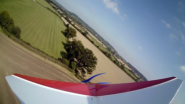
I wanted to add an 808 Key-chain camera on top of the fin to record some flight video so I made a small platform from foam board and taped it in place. The extra tail weight was balanced by replacing the 3S 1300 mAh battery with a 2200 mAh. There was no noticeable change to the flight behaviour, but the resulting video showed continuous wing wobble. This was actually an illusion of relative motion as it was the fin that was wobbling. I braced the fin with some diagonal BBQ skewers to the horizontal stabilizer and the wobble disappeared.


I’ve been very pleased with these two models. They fly well and have proven very resilient. The Flyer survived two tree landings and extractions with only a broken prop. The only problem has been summer heat. It turned out the black foam board’s paper was attached with hot melt glue. After sitting in the car for a morning it all detached. The white foam board doesn’t have this problem and is still going strong.


I have since managed to obtain some Bazic branded Adams Ready-Board from which I have built an FT Bloody Wonder (Mk3), another great flyer. I’m thinking of scaling it up for the heavy foam board, possibly with twin engines so I can use it as an FPV platform.
During the winter my local RC club has an indoor session once a month a bowls hall. This is crown bowls, rather than 10-pin. Small quadcopters are popular at these meetings and post Christmas, there are now three Blade Nano QX FPV quads. Now obviously whenever you have two or more FPV quads in one place there will be a desire for racing or at least some close proximity flying. So an idea was born for a nano size FPV course, that would fold up small for easy transportation. Additionally, it had to be cheap, preferably using materials I already had.
While the final package is a little bigger than I had originally hoped, it was cheap, quick to erect and still easily transportable in an 1/8 scale car carry bag.
I found some 12mm pine shelf and some orange ripstop nylon. To this I added a pair of telescopic magnetic pickups for about £2 each. These extend from 133mm to 645mm and are rated to lift 3.5kg. The board was cut into trapezoids to maximize its use and a 10mm hole drilled near the back edge to accept the pickup, once I had removed the pen clip. Some velco was added to the front edge and I got a sleeve cut out and sewn up, to form a mini corner pennant.
I had though to string a ribbon between two pennants to form a gate, but by the time the ribbon was deep enough to be clearly visible through a nano FPV camera, combined with it’s droop, there was only a small gap to fly under.
I found some bigger telescopic pickups at CPC Farnell that extend from 165 to 838mm. The original base was not thick enough for the bigger pickup as it was 16mm diameter with a domed end. I had some 1¾” x 5/8″ (45mm x 16mm) timber which I used to extend the mounting hole, however, I felt the base was not wide enough for stability. I had plenty of the 1¾” x 5/8″ so I cut it into two 8″ (200mm) lengths and a 1¾” (45mm) square. These were glued and nailed together and drilled through until the point just started to show.

Three generations of base.

Size comparison.

Transportation size.
As you can see these pennants fold down really small. I couldn’t find a good solution to make the new bigger pennants into a gate, but one of the solutions I did considered was to use foam board as a beam between the pickups and this gave me an idea.
I had a stock of 5mm foam board that was too heavy for making into aircraft, but which was idea for FPV gates. It was A1 size (840 x 597mm) which produced a nice size gate. They are a lot bigger for transportation, but still very light. I used red and yellow parcel tape to make them highly visible.
For a start/finish gate I printed some A3 chequered pattern sheets that I glued onto the foam board and then covered with clear packing tape.
The foam board was cut to the sizes shown below which can be adjusted to suit your available foam board and timber. The 50% score cuts were folded back to form a hinge which was reinforced with clear tape on both sides. Small 20mm x 80mm rectangles of foam where added to give a bigger mounting point for the cross members. These were covered with tape and then more tape was used to fix them in place.
Bases for these gates where made from the same 1¾” x 5/8″ (45mm x 16mm) timber. One 10″ (250mm) length and three 1¾” (45mm) blocks. The 20mm dimension on the foam board can be adjusted to suit your timber thickness. It can be a little bigger than your timber but not smaller. Once it’s assembled give it a good sanding to smooth off the edges.

Foam board column base


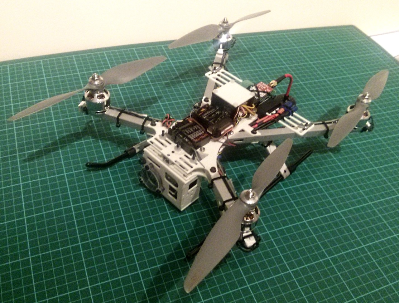
I set up a small quad with a contemporary FPV system. In this case an 25mW ImmersionRC video transmitter using my GoPro 3 Black as the camera. I had wanted to compare the latency of this system against that of the Raspberry Pi. The problem is that I can’t use the GoPro to measure the latency of itself. I need to see if I can borrow another one. For now it was just nice to get out and fly.
The quad is a Quadrixette 30 from http://www.eyefly.info. It’s quite an old design now, but I like it because it is small (300mm), but still bale to carry some weight. The flight controller is a OpenPilot CC3D and I’m using a Spektrum AR8000 receiver with telemetry module to report the flight battery voltage.

One of my club mates was also at the field with his Tricopter so we had some proximity flying.
Up to now I have been using an Edimax EW-7812UAn V2 USB WiFi Dongle. This has been very reliable and reasonably simple to install and configure. The only problem is that it operates on the 2.4 GHz frequency band, which means it will interfere with the majority of modern radio control systems. Up to now I have been using a 35 MHz RC system which was fine as long as I was flying on my own. However, I’d like to fly with others who will be using 2.4 GHz systems.
There are now a number of Dual Band Wifi Dongles that operate in the 5 GHz band as well as at 2.4 GHz. This provides a solution so long as they work with the Raspberry Pi. A couple of candidates were obtained, configured and tested on my Model B Raspberry Pi. For an extra comparison I also ran a test over the wired LAN interface.
The results were interesting in that there was no clear winner in the speed stakes, there was however a clear loser. What is clear is that useable 5 Ghz WiFi is possible but for now it’s not plug and play.
For these tests I used the following network devices.
I setup my Model B, with the latest release of Raspbian (2015-01-31) and the current scripts.
To get 5GHz WiFi working you need to install the Central Regulatory Domain Agent (crda). Basically, the 5 GHz band is more tightly regulated worldwide and you need to specify your regulatory domain so that hostapd knows which channels are available.
To install the necessary packages use:
sudo apt-get install hostapd crda iw
Then edit /etc/default/crda and set the REGDOMAIN variable to match your region. Examples are US, JP, EU and in my case UK.

The amount of work needed to setup networking varied by device. I’m not going to give a detailed description of configuring each device. I’ll do that in separate posts.
1. LAN
This simply required plugging the Pi and the Laptop into a switch and running ipconfig on the receiving device to get its IP address. This was then used in remote.conf to direct the UDP stream.
2. Tenga W522U
The W522U is nl80211 compatible. This means it works with a standard install of hostapd. No special configuration is needed.
3. Edimax EW-7612UAn V2 (2.4 GHz)
The EW-7612UAn V2 uses the RTL8191SU chipset. The kernel supports this chipset for client networking, but not for AP mode. However, Realtek provide a custom version of hostapd that needs to be downloaded, compiled and installed which does work.
4. Edimax AC600 Dual Band (2.4 GHz & 5 GHz)
The AC600 is not supported by the latest kernel. All is not lost, it just takes a little more work. You need to download the kernel source code and the code for a Realtek 8812U driver. Then you need to install the latest version of GCC from the Jessie repository. This lets you build the kernel module. Finally you need the same hostapd build as for the Edimax EW-7612UAn V2 device.
There are four combinations of hostapd.conf depending on the driver and band. I’ve set them out in the table below.
| Hostapd Version | 2.4 GHz | 5 GHz |
|---|---|---|
| nl80211 |
interface=wlan0 driver=nl80211 ssid=Pi_AP hw_mode=g channel=13 macaddr_acl=0 auth_algs=1 ignore_broadcast_ssid=0 wpa=2 wpa_passphrase=Raspberry wpa_key_mgmt=WPA-PSK wpa_pairwise=TKIP rsn_pairwise=CCMP |
interface=wlan0 driver=nl80211 ssid=Pi_AP hw_mode=a channel=44 ht_capab=[HT40+] ieee80211n=1 macaddr_acl=0 auth_algs=1 ignore_broadcast_ssid=0 wpa=2 wpa_passphrase=Raspberry wpa_key_mgmt=WPA-PSK wpa_pairwise=TKIP rsn_pairwise=CCMP |
| Realtek |
interface=wlan0 driver=rtl871xdrv ctrl_interface=/var/run/hostapd ssid=Pi_AP channel=13 beacon_int=100 hw_mode=g ieee80211n=1 wme_enabled=1 wpa=2 wpa_passphrase=Raspberry wpa_key_mgmt=WPA-PSK wpa_pairwise=CCMP max_num_sta=8 wpa_group_rekey=86400 |
interface=wlan0 driver=rtl871xdrv ctrl_interface=/var/run/hostapd ssid=Pi_AP channel=44 beacon_int=100 hw_mode=a ieee80211n=1 wme_enabled=1 ht_capab=[SHORT-GI-20][SHORT-GI-40][HT40+] wpa=2 wpa_passphrase=Raspberry wpa_key_mgmt=WPA-PSK wpa_pairwise=CCMP max_num_sta=8 wpa_group_rekey=86400 |
These tests were a straight comparison between the four devices using the same settings and the same testing methodology as previously. The resolution was 1280 x 720 pixels with a 6Mbps bit rate.
The table below shows the resulting latency by device.
| Device | Latency |
|---|---|
| Edimax EW-7612UAn V2 – 2.4 Ghz | 132 ms |
| Tenga W522U – 2.4 GHz & 5 GHz | > 10 s |
| Edimax AC600 – 2.4 GHz | 122 ms |
| Edimax AC600 – 5 GHz | 126 ms |
| LAN | 124 ms |
Here they are as a graph.

The big surprise is how bad the Tenga W522U adapter was. The latency was not just two or three times higher, it was two order of magnitudes higher. There are a number of threads on various forums where other people have found similar issues, although not to this extent, but then they are probably not swamping the feed with a continuous video stream. Whether this is just a compatibility issue with the Pi remains to be seen.
The Edimax AC600 was 10 ms faster than the previously used Edimax 7612UAn V2 at 2.4 GHz. At 5GHz it was still faster, but only by 6ms. Interestingly, the LAN connection was not any faster than the AC600. On the Pi the LAN connection is 100 MBit/s as is the USB bus, so although the AC600 is theoretically capable of 433 Mbit/s it is never going to manage more than 100.
What we can take away from this test is that there is a limit to how much the latency can be reduced by changing the WiFi adapter. It is a shame that to get a 5 GHz WiFi link requires a lot of compiling and configuration. Hopefully this will improve with time. For now we have another small reduction in the video latency to add to the current optimisations.
Just as these tests were being done, the new Raspberry Pi 2 was released promising a x1.5 to x6 speed increase. As I had used the latest release of Raspbian, I swapped the microSD card from from the Model B to the Model 2B. What I found was that the Edimax AC600 was no longer detected and I couldn’t find a way to compile the module so that it would. So that’s my next task. I may run a quick comparison of the B versus the 2B with the Edimax 7612UAn V2 to see how much improvement the new processor has made.
The aim of this flight was to test the airframe and the electronics after the unplanned lawn dart into the mud. It was also the first test of the CRIUS CN-06 V2 U-blox GPS module. I didn’t bother to stream the video to the laptop. Instead I used the JuiceSSH app on my phone to access the Raspberry Pi and start a local 1080p HD and GPS recording.
The Crius GPS cable terminates in a standard 0.1″ pitch, four pin socket. The pin outs on the Raspberry Pi are spread out over five pins, so I borrowed a single socket housing from a PCB development jumper and re-arranged the connections as shown in the photo below.

The GPS was held on to the case with BluTak.
The only other change was to mount the camera on an extension so I could point it further down and to the right. The aim being to get the propeller out of shot.
I didn’t plan for any big tests on this flight so didn’t bother setting up the laptop. Instead I used the JuiceSSH app on my phone to start recording the GPS and video output on the Pi using a short script. As I wasn’t streaming the video, I bumped the resolution up to full 1080p.
#!/bin/sh
cat $0

# Zero duration is continuous
DURATION=0
WIDTH=1920
HEIGHT=1080
FRAMERATE=25
BITRATE=10000000
NOW=`date +%Y%m%d%H%M%S`
FILENAME=$NOW-Pi.h264
gpxlogger -i 2 -f $NOW-Pi.gpx &

/opt/vc/bin/raspivid -t $DURATION -w $WIDTH -h $HEIGHT -fps $FRAMERATE -b $BITRATE -n -o $FILENAME
Almost immediately I felt something wasn’t working properly. Whilst the model was flying at normal speed, the climb rate was very low. The wind wasn’t as strong as previously, but there still seemed to be some significant turbulence tossing the plane around. After only one and a half circuits it started descending whilst over the far boundary and landed in a tree.

The only visible damage was a broken tailplane and a broken prop. I still had a WiFi connection from my phone to the Pi and was able to stop the recording and shut it down. I had a 4m long strap in the car with a heavy buckle on one end, but it wasn’t long enough to reach the plane. As this was lunchtime, I eventually had to leave it up the tree and return to work.
After work I stopped in at a local hardware store and bought 15m of chord and a pack of 10mm shackles. The plane was still up the tree when I got back to the field, so I tied two of the shackles chord and started launching it skywards. I soon found out I needed to tie some shackles to the loose end to stop the whole lot ending up in the tree. After about 10 minutes, I managed to get the chord over the fuselage and pull it free of the branches.
After disconnecting the battery, a more detailed examination revealed the only other damage as a dent in the nose. As the ESC had been connected for five hours, the battery had continued to drain and when checked was well past the minimum voltage. One of the cells was reading 2.15V, so that battery will be going for recycling.
I was able to extract the video and gps files from the SD card. It turns out the propeller was still partly visible in the video and because of this I could see the low voltage cutout had activated just as the plane crossed the far boundary. This is why it started descending and ended up in the tree. Why the battery went flat so quickly was another matter, as was the lack of power and the inability to climb.
Once I got everything on the bench I found the motor felt a bit rough. I can only assume that grit had got into the bearings after the mud bath. This could account for the increased current draw with the reduced power output.
I think pointing the camera off to the side was a bad idea, even for a non FPV flight.
The one positive result was the CRIUS GPS. There was an excellent correlation between the video and the GPS track, as the two pictures below show.


Additional benefits for the CRIUS are:
From now I shall be using the CRIUS GPS.
As the aircraft needs some rebuilding, I’m going to rework the internals so that I can mount the Raspberry Pi internally, with the camera above the nose. I also need to build a new power pod the will mount above the wing.
As an alternative platform for some actual First Person View flying, I’m also building a tricopter.
After much trawling through the forums, I found a way to record the video stream at the receiving end using gst-launch-1.0 in such a way that it can be converted to a playable format later on without re-encoding and the resulting loss of quality. Eventually, replacing gst-launch-1.0 with a dedicated gstreamer application would allow a valid video file to be recorded straight from the stream without the current post processing. This flight also included a test of the external amplified antenna for the Ultimate GPS Breakout board. The results were disappointing, not attaining sufficient accuracy for the desired application. The flight was cut short due to a combination of high, turbulent wind and dumb thumbs, but was long enough to get meaningful results. You need to watch the video at 720p for a meaningful comparison. Please bear in mind that the video has been re-encoded at least once, possibly three times between the Pi and your browser. https://www.youtube.com/watch?v=eCazn-JbR_0
The amplified GPS antenna comes with 5 metres of cable and a heavy magnet. I shortened the cable and removed the magnet, but the parts were still unwieldy when strapped to the top of the plane. Hardware wise this was the only addition to the previous test. 
I had already generated and swapped ssh keys between the Pi and the laptop to remove the need to enter a password when connecting. While I’ve been testing different GPS setups , I’ve started gpsd using a small shell script
#!/bin/bash
echo Starting gpsd
sudo gpsd /dev/ttyAMA0 -n -F /var/run/gpsd.sock
I want to use the current time and date for the video and gpx file names. As the Pi does not have a real time clock, I set the time from GPS using a script based on one I found at http://blog.petrilopia.net
#!/bin/bash
sudo date -s '01/01/2014 00:01'
sleep 1
GPSDATE=`gpspipe -w | head -10 | grep TPV | sed -r 's/.*"time":"([^"]*)".*/\1/' | head -1`
echo $GPSDATE
sudo date -s "$GPSDATE"
Next I run cgps to check the GPS accuracy. Once it stops improving I exit cgps and run the third script to start gps logging and record the video stream. The video is recorded as the raw h264 stream with a Tx (Transmitter) suffix.
#!/bin/sh
cat $0

# Duration in milliseconds. Use 0(Zero) for continuous
DURATION=1800000
WIDTH=1280
HEIGHT=720
FRAMERATE=25
BITRATE=2500000
NOW=`date +%Y%m%d%H%M%S`
FILENAME=$NOW-Tx.h264
gpxlogger -i 2 -f $NOW.gpx &
IP=$(ip -o addr show wlan0 | sed -n 's/.*inet \([0-9.]*\)\/.. .*/\1/p')
PORT=5000

/opt/vc/bin/raspivid -t $DURATION -w $WIDTH -h $HEIGHT -fps $FRAMERATE -b $BITRATE -n -o - | tee $FILENAME | gst-launch-1.0 -v fdsrc ! h264parse ! rtph264pay config-interval=1 pt=96 ! gdppay ! tcpserversink host=$IP port=$PORT
Finally, back on the laptop, in a new terminal window, I run a script to capture and display the video stream. The h264 file is multiplexed (muxed) into an mpeg transport stream (ts) container with a Rx (Receiver) suffix.
#!/bin/bash
# Read the Settings file
source ./settings.conf

# Set file name from current time
NOW=`date +%Y%m%d%H%M%S`
FILENAME=$NOW-Rx.ts

# Read the stream.
gst-launch-1.0 -v tcpclientsrc host=$IP port=$PORT ! \
 gdpdepay ! rtph264depay ! \
 h264parse config-interval=96 ! \
 tee name=t ! queue ! \
 video/x-h264, framerate=25/1 ! avdec_h264 ! videoconvert ! autovideosink sync=false t. ! \
 queue ! mpegtsmux ! filesink location=$FILENAME

# Try to copy the file from SD card to Hard Disk
if [ ! -d $TARGETDIR ]; then
 sudo mount /dev/sdb4 /mnt
fi
cp $FILE $TARGETDIR/$FILENAME
Here is a sample settings.conf
#!/bin/bash
export IP=192.168.42.1
export PORT=5000
export FRAMERATE=25
export TARGETDIR=/mnt/home/user
The Flight
When I arrived at the field the wind felt to be blowing at a constant 10 mph. In the short time it took to get everything ready it had started gusting much harder. Having driven to the field and got everything setup I was determined to fly so opened the throttle and gave it a good chuck. My first realisation was that the wind was stronger than anything I had flown in before. In order to get the aircraft to track up the field and not be blown out the back, I had to point it 20 to 30 degrees past the desired direction of flight. Also, as the aircraft got further up the field and closer to the trees, the turbulence made it harder to control. Eventually, it got bucked around to the point I lost orientation, dumb thumbed the rudder flipping it upside down and I wasn’t able to recover it before it hit the ground. When I checked later, the met office were quoting 26 mph gusts.
The previous months rain had softened the ground enough that the aircraft nose was stuck in three or four inches with no apparent damage. The rubber bands had separated, releasing the wings. Any electronics that weren’t screwed down were scattered around the crash site and given a liberal coating of mud. Everything was dismantled and cleaned in fresh water, then left to dry. When I did reconnect everything, it all worked. The only problem was that camera now has a green tint. I suspect that that the mud has abraded the lens coating, either on impact or during cleaning. As they are cheap I bought a new one.
I was worried that the crash would have lost or corrupted the on-board video recording. As it turned out, only the last few seconds of the flight were lost, as you can see in the video. After collecting the scattered components, I found the X terminal on the laptop reporting that the SD card had become read only. It was still receiving and recording a video stream, although this was mostly a totally brown frame which turned to a greeny orange when I removed most of the mud.
I’ll cover the GPS first as it’s going to be short. The results using the larger amplified antenna were better, but still not good enough. There seems to be either a lag or an offset in the computation. The two images below show the problem. For the next flight I’m going to use the CRIUS CN-06 V2 U-blox GPS module. 

The video recorded on the Pi (Tx) was copied to a Windows PC using WinSCP. Then I used MP4BoxGUI to mux it into a MP4 file. I have not had any problems using the generated file. With the video recorded on the laptop (Rx) as a transport stream, the first task was to convert it into an mp4. The following script takes the file name as an argument and creates two new videos. This need to be run on a machine using Gstreamer version 1.2 (Check using gst-launch-1.0 –version).
#!/bin/bash
echo .
echo Remux
echo .
gst-launch-1.0 -v filesrc location=$1 ! tsdemux ! h264parse ! video/x-h264,framerate=25/1 ! mp4mux ! filesink location=$1.remux.mp4
echo .
echo Re-encode
echo .
gst-launch-1.0 -v filesrc location=$1 ! tsdemux ! h264parse ! video/x-h264,framerate=25/1 ! avdec_h264 ! videoconvert ! x264enc bitrate=2500 ! mp4mux ! filesink location=$1.reenc.mp4
The first gstreamer pipeline (Remux), simply extracts the h264 video from the transport stream container and them multiplexes it into an mp4 container. The h264 stream is unchanged, so there is no loss of video quality. To make this file viewable on Windows required a couple of extra steps. With the file copied on to the Windows PC I used MP4BoxGUI to demux and extract the h264 stream (again) and then to Mux it back into an MP4 file. This new file was playable in Windows media Player. The second gstreamer pipeline (Re-encode), re-encodes the video as a new h264 file and multiplexes it into an mp4 container. While re-encoding has to reduce the picture quality, it is not obvious without close inspection. I use the re-encoded video in Sony Movie Studio 11.0, which had trouble reading the first remuxed file. I also had to manually set the frame rate in Sony Movie Studio 11 to 25 fps as by default it was using 29.97 fps making it impossible to sync the Tx and Rx videos together.
The video posted on Youtube shows the Tx and Rx videos side by side. They are fully synced and without a gap between I don’t think you can spot a join or see any difference in video quality. Although a bit of a faff, for now I have a working pipeline to record usable video on the ground. As for the GPS, the search goes on.

You must be logged in to post a comment.