
Introduction
During the winter my local RC club has an indoor session once a month a bowls hall. This is crown bowls, rather than 10-pin. Small quadcopters are popular at these meetings and post Christmas, there are now three Blade Nano QX FPV quads. Now obviously whenever you have two or more FPV quads in one place there will be a desire for racing or at least some close proximity flying. So an idea was born for a nano size FPV course, that would fold up small for easy transportation. Additionally, it had to be cheap, preferably using materials I already had.
While the final package is a little bigger than I had originally hoped, it was cheap, quick to erect and still easily transportable in an 1/8 scale car carry bag.
Components
I found some 12mm pine shelf and some orange ripstop nylon. To this I added a pair of telescopic magnetic pickups for about £2 each. These extend from 133mm to 645mm and are rated to lift 3.5kg. The board was cut into trapezoids to maximize its use and a 10mm hole drilled near the back edge to accept the pickup, once I had removed the pen clip. Some velco was added to the front edge and I got a sleeve cut out and sewn up, to form a mini corner pennant.
I had though to string a ribbon between two pennants to form a gate, but by the time the ribbon was deep enough to be clearly visible through a nano FPV camera, combined with it’s droop, there was only a small gap to fly under.
I found some bigger telescopic pickups at CPC Farnell that extend from 165 to 838mm. The original base was not thick enough for the bigger pickup as it was 16mm diameter with a domed end. I had some 1¾” x 5/8″ (45mm x 16mm) timber which I used to extend the mounting hole, however, I felt the base was not wide enough for stability. I had plenty of the 1¾” x 5/8″ so I cut it into two 8″ (200mm) lengths and a 1¾” (45mm) square. These were glued and nailed together and drilled through until the point just started to show.

Three generations of base.

Size comparison.

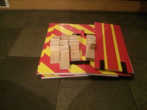
Transportation size.
As you can see these pennants fold down really small. I couldn’t find a good solution to make the new bigger pennants into a gate, but one of the solutions I did considered was to use foam board as a beam between the pickups and this gave me an idea.
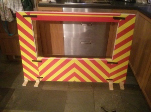
I had a stock of 5mm foam board that was too heavy for making into aircraft, but which was idea for FPV gates. It was A1 size (840 x 597mm) which produced a nice size gate. They are a lot bigger for transportation, but still very light. I used red and yellow parcel tape to make them highly visible.
For a start/finish gate I printed some A3 chequered pattern sheets that I glued onto the foam board and then covered with clear packing tape.
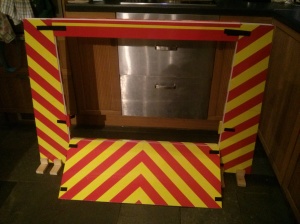
The foam board was cut to the sizes shown below which can be adjusted to suit your available foam board and timber. The 50% score cuts were folded back to form a hinge which was reinforced with clear tape on both sides. Small 20mm x 80mm rectangles of foam where added to give a bigger mounting point for the cross members. These were covered with tape and then more tape was used to fix them in place.
Bases for these gates where made from the same 1¾” x 5/8″ (45mm x 16mm) timber. One 10″ (250mm) length and three 1¾” (45mm) blocks. The 20mm dimension on the foam board can be adjusted to suit your timber thickness. It can be a little bigger than your timber but not smaller. Once it’s assembled give it a good sanding to smooth off the edges.

Foam board column base
Start/Finish Gate


High Gate


Low Gate


The Plans


You must be logged in to post a comment.